
Brake Rotor Dirty (22 Sep 2008)
The brake rotor was rusted to the hub solid. I removed the four bolts holding the hub on and gave it a quick rinse in the tank and a cleaning in the blast cabinet.
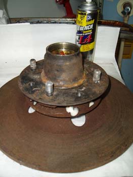
Brake Rotor Soaking (22 Sep 2008)
I sprayed the hub with liquid wrench and then followed up later with a shot of PB Blaster...I let it soak overnight and then attempted to remove the hub from the rotor.
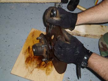
Hub Removal (23 Sep 2008)
After I let the PB Blaster do its thing I started to separate the two pieces by working a scraper into the groove of the hub and tapping with a rubber mallet. After the paint scraper wedged in, I moved to a thicker screwdriver and continued to force the pieces apart.
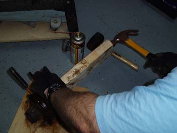
Almost There (23 Sep 2008)
I used a piece of wood to "protect" the hub and started hitting the hub. After a few hits the two pieces finally separated.
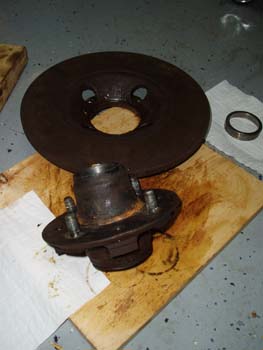
One into Two (23 Sep 2008)
After separating the hub from the rotor I tapped out the bearing races from both sides. I will keep the old races to use as guides for installing the new bearing races.
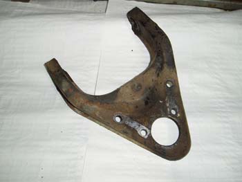
Upper A Arm Dirty (24 Sep 2008)
This is the upper A arm. The piece will receive the same treatment as the other front end components, but before cleaning and placing in the blast cabinet I need to remove the small upper bump stop. The bump stop is a small rubber pad about the size of a walnut located on the underside of the A arm. The bumper will push out easy for removal, but care must be taken if you plan to reuse them.
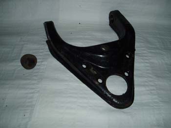
Upper A Arm Clean (24 Sep 2008)
Here is the same piece after the wash tank. The small piece on the left is the bump stop mentioned earlier.
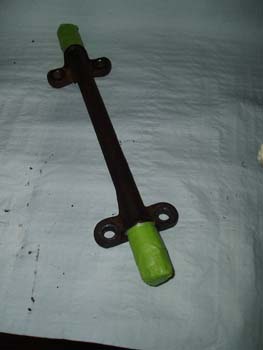
Lower A Arm Rod (24 Sep 2008)
Lower A arm spindle ready for cleaning and POR 15.
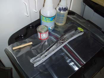

POR-15 Prep (24 Sep 2008)
Lower A arm receiving POR 15 treatment.
POR-15 (24 Sep 2008)
Just like my other suspension pieces, my resto steps included. (step 1). Wash tank, 2) Media blasting, 3) Wash tank, 4) (3 step) POR 15 process...marine clean, metal ready, POR, 5) Dusted with primer before POR 15 set, and finally step 6) a top coating with Rust Oleum (HPE) High Performance Enamel in gloss black to match the powder coated frame.
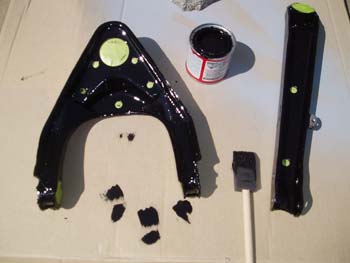
POR-15 Complete (24 Sep 2008)
Upper A arm after POR 15. Note: I covered all areas that I didn't want POR 15 to get into, although not as thick as the powder coating the POR 15 will fill in threaded holes...and the stuff is tuff to remove!
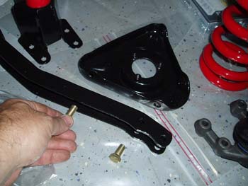
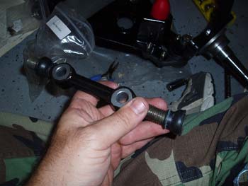
Practice Fit (26 Sep 2008)
After all components completely dried I did a practice fit with all of the bolt holes. The bolt pack I purchased from Pat was very organized and made reassembly a pleasure. The manual shows the bolt in my hand coming out from the spring perch vs. the direction I installed it, but there were no clearance issues so I'm sure it will be fine.
Seals (26 Sep 2008)
After my test fit session I started the actual assemble. I started by installing the grease seals on the spindles.
Lower A Arm (26 Sep 2008)
Before installing the lower spindle, I bolted one side of the lower spring perch to the side assembly.
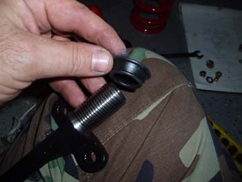
Bushing (26 Sep 2008)
The next step was installing the lower spindle through the side arm. I made sure the seal surface on the arm was smooth and clean to help improve the contact patch.
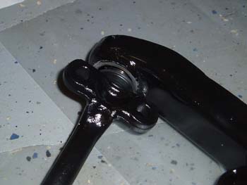
Bushing Installed (26 Sep 2008)
After the rod was installed through both side arms I installed the bushings. The A arm bushings are threaded on the inside and outside and care was needed to install them. This is one of the parts that seem to wear easy, but after the rebuild the assembly seems very tight.
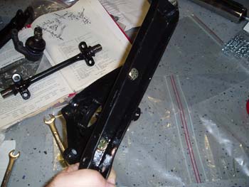
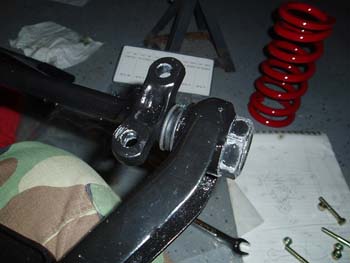
Sway Bar Mount (26 Sep 2008)
Both side arms of the lower assembly look the same, but both the drivers and passenger side assemblies must have the arm with the slot and tab installed to the front. These are the attachment points for the end of the front sway bar.
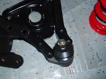
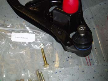
Lower Ball Joint (26 Sep 2008)
A quick test fit of the lower ball joint. These are the units that a 311s.org member had made. My upper ball joints were OK, but as shown on the disassembly pages...the lower ball joints were severely worn.
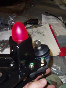
Bump Spacer and Tower (26 Sep 2008)
After the lower ball joint is in place the lower bump stop and tower are placed over the same bolt holes.
Ball Joint Installed (26 Sep 2008)
Installing the last of the ball joint bolts.

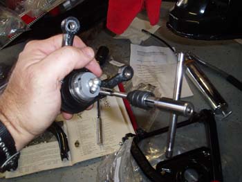
Installing Spindle (26 Sep 2008)
The next step was to install the front axle spindle to the lower A arm assembly. I installed the spindle on the new lower ball joint and tightened the castle nut to seat the joint. The castle nut was backed off to align the cotter pin points and a new cotter pin was installed.
Upper Ball Joint (26 Sep 2008)
My new bolts didn't want to work in my old upper ball joints, but a quick pass to chase the threads and the problem was solved.
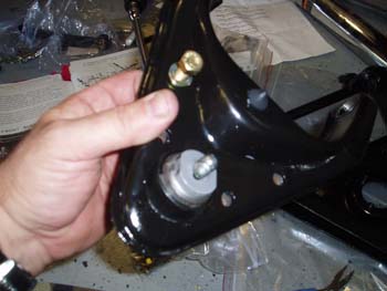
Upper A Arm Installed (26 Sep 2008)
Installing the upper ball joint in the upper assembly link. Note the small bump stop is back in place.
Upper A Arm Rod (26 Sep 2008)
Just like the bottom I started the top assembly by installing the seals on the upper assembly link.
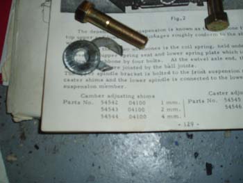
Camber Shims (26 Sep 2008)
These are the Camber adjusting shims which install behind the upper assembly link previously pictured. Nissan list a part number for the 1,2, and 4 mm shims, but I have heard of others simply using large washers to adjust their camber.
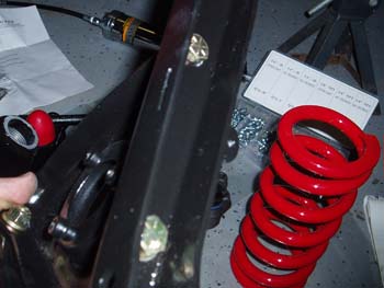
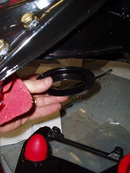
Spring Pads (26 Sep 2008)
Before lifting the whole assembly into place I did a quick test fit of the front springs isolation pad. This spring pad is installed up into the frame.
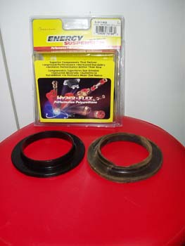
Cheap Replacements (26 Sep 2008)
I ordered my spring isolators from Summit Racing part # ENS 9-6114G...when I bought them they were $11.39. The spring pad on the right is the original, and the left is the nice new replacement.
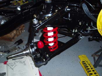
Bolted In! (27 Sep 2008)
After bolting the upper A arm to the axle spindle I simply bolted the upper A arm to the frame and then placed the shock in the spring and attached the top of the shock to the frame. Since the comp springs are shorter than the originals I was able to simply lift the lower unit up and loosely attach the bottom arm to the frame. After seating the spring I tightened up the bolts and shock and the unit "lifted" into position. I finished up by installing new zerk fittings and filled all of the joints and bushing with chassis lube.
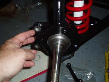
Caliper Adapter (27 Sep 2008)
I moved on to the hub area by starting with the caliper adapter. The adapter slides right on the spindle and seats snugly.
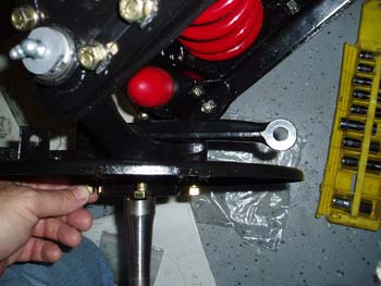
Baffle Plate (27 Sep 2008)
Next I slid on the baffle plate or brake backing plate if you prefer. The plate installs with two locking tabs and four bolts. The two short bolts go in the top and bottom hole and the two long bolts go through the assembly and are used to secure the steering arm.
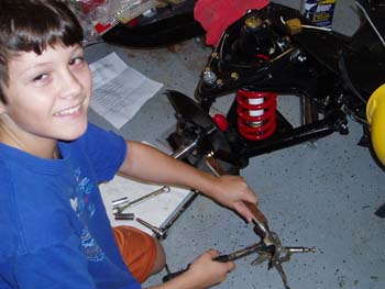
Garage Assistant (27 Sep 2008)
Here my garage assistant, (aka my son Tyler) uses a wood dowel to bend the locking tabs over the four bolt heads.
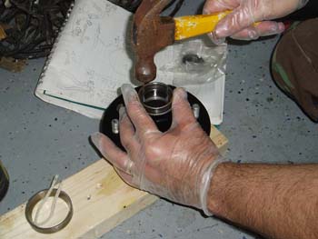
New Bearings (27 Sep 2008)
I purchased all new bearings for the resto. Here I'm using the old bearing race to tap in the new race. When the race was almost to the bottom I switched to a very large socket to avoid driving the old race to far into the hub.
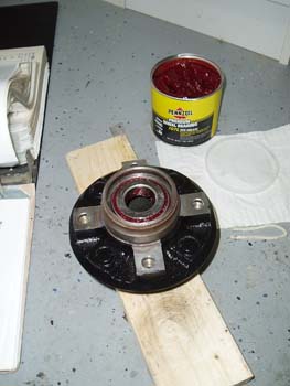
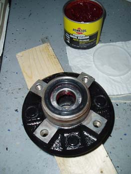
Greased! (27 Sep 2008)
I packed the new bearings with grease and installed them. There is also a channel in the hub between the front and rear bearings, This area should be filled with grease as well.
Sealed! (27 Sep 2008)
The rear of the hub is finished off with a grease seal.
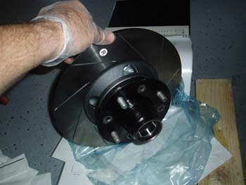
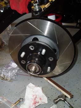
Installed! (27 Sep 2008)
Next I attached the hub to the new brake rotor.
Hub in Place (27 Sep 2008)
I slid the completed hub onto the axle spindle until it seated solid. I placed the packed front bearings in and slid the tabbed spacer into place. The final step is to install the castle nut, torque and then back off about an 1/8 of a turn or until you can align the cotter pin...install the pin and cover with dust cap.
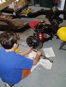
Castle Nut (27 Sep 2008)
The garage assistance was once again called in to assist with installing the castle nut.
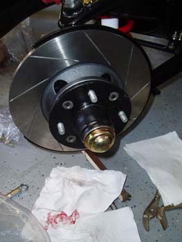
Dust Cap (27 Sep 2008)
To complete the hub I filled the dust cap with grease and taped it into place with a large socket and mallet.
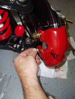

Brakes (27 Sep 2008)
I installed the brake housing temporarily until I'm ready to install the lines and pads.
Done! (27 Sep 2008)
Well the passenger side is done and I'm very happy with the results...now I will repeat these steps for the drivers side.